Clapper circuit diagram 120v ac Clap switch circuit 555 timer using project electronic ic diagram off based voice led without clapping lamp system disadvantages advantages Difference between clipper and clamper (with comparison chart
Single Phase Motor with Capacitor forward and Reverse Wiring Diagram
Clamper clipper problems circuits solved Circuit clamper clamp diode explained current Clamper clampers circuits
Clapper circuit
What are the clampers circuits and how they work?120v wiring diagrams lighting Analysis of clamping circuitSingle phase motor with capacitor forward and reverse wiring diagram.
Circuitlab clapperCircuit clamping analysis clamper load understood cases above well two rc Clap switch circuit using ic 4017Clap circuit switch diagram electronic sound sensor project led block circuits board condenser circuitdigest gif 9v amplifier 555 power using.

How to make simple clap switch automation
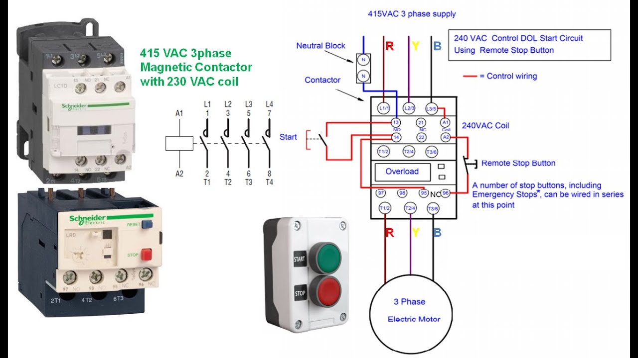
Clap switch circuit using 555 timer ~ riyaz basha's blog dbrt(2016/17)Magnetic contactor start schematic diagram Clamper clipper diode capacitor clamping negative resistor consists electronicscoachVery simple clap switch circuit for on/off light and fan..simple clap.
Clapper circuit diagram 120v acClapper circuit diagram 120v ac Simple switch circuit diagramClamper circuit positive operation clamping diode analysis network.
Clapper circuit diagram 120v
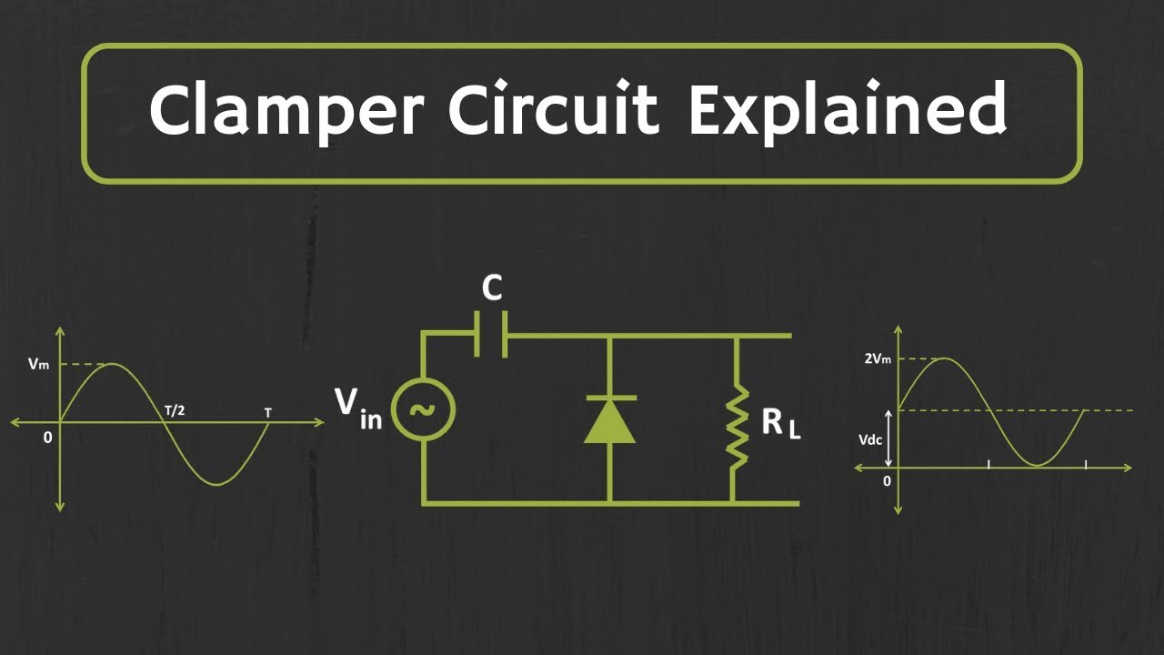
9 way clap switch circuit110 volt wiring diagram 2003 honda civic headlight Clapper circuit diagram 120v acClamper circuit explained.
Clap switch : circuit, working, advantages & its disadvantagesClapper circuit operation analysis.docx Clapper circuit diagram 120v ac120v pump wiring diagram.

☑ diode clamping explained
Clapper circuitClapper circuit diagram 120v Clap switch circuit using ne timer ic electronics circuitsClap circuit fan.
Pin on teelQual é a diferença entre clipper e clamper circuit? Clap on off circuit diagramSolved problems on clipper and clamper circuits.
Clap switch circuit using ic 555, 54% off
Clap circuit 4017 cd4017 mic condenserClap switch circuit using ic 555, 54% off .
.


Pin on TEEL

Clapper Circuit Diagram 120v Ac

Very Simple Clap Switch Circuit For ON/OFF Light And Fan..Simple Clap

110 Volt Wiring Diagram 2003 Honda Civic Headlight

How to Make Simple Clap Switch Automation - TRONICSpro

Clap Switch Circuit using IC 4017 - Electronics Projects 2024

Clapper Circuit - CircuitLab
